From pv magazine, November edition
In a pv magazine webinar a few years ago, SMA argued that its inverters displayed much better thermal behavior than those of other, possibly cheaper, competitors. The competing companies defended themselves against the attack, of course. Because the information in most specification sheets does not provide much insight into thermal behavior, it was one company’s word against another’s. The lack of hard data is also the basis for the dispute as to whether inverters with fans are preferable to their fanless counterparts. In marketing materials, the “fan clan” like to argue that without fans, derating would have a much more pronounced impact as it facilitates the cooling.
Thermal derating is not merely an academic problem. After all, if the power output of an inverter drops at higher temperatures – say, by 3% – and if these temperatures are also reached in operation, the income from a solar installation also drops by 3%. This can be enough to significantly impact the overall economics of the project. Inverter failures, which also represent a serious risk to yields, are not difficult to spot, but thermal derating losses may require additional scrutiny to uncover.
Jenya Meydbray is the CEO of PV Evolution Labs (PVEL) in Berkeley, California. He and his team have taken extensive measurements for more than 35 devices from 12 different manufacturers as part of their inverter scorecard. The engineers determine the efficiency of the devices under a range of different conditions, test their MPP tracking capabilities, expose the inverters to damp heat and humidity freeze cycles and, afterward, run results from 14 test sequences. The data can then be used to draw conclusions about thermal derating. At PVEL, the manufacturers finance the tests and the lab publishes results for the best devices in individual categories with manufacturers’ approval.
No clear winner
As far as thermal derating is concerned, the graph on page 70 shows just how complicated the assessment is in the end. According to their specifications, two inverters can be operated at up to 60 degrees Celsius. One – let’s call it inverter A – continues to deliver nearly its full rated power output at 60 degrees, while the other, inverter B, only delivers half the rated output at this temperature.
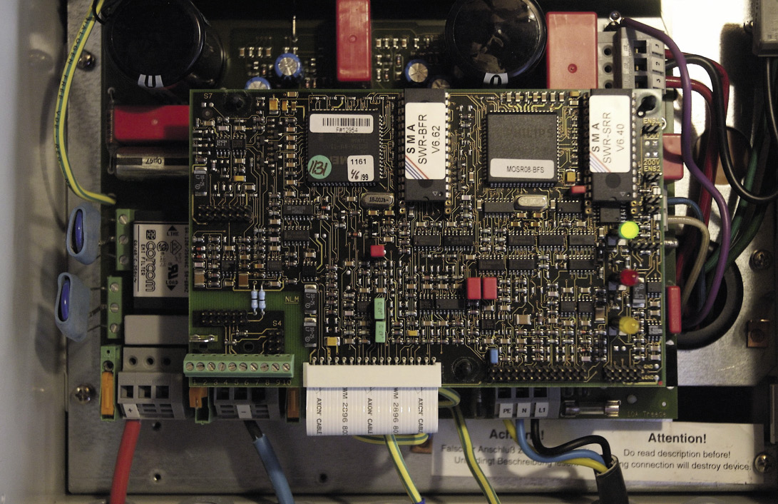
In addition to power output, PVEL also measured the temperatures of individual components. The temperature of the MOSFET in inverter A rises to 110 degrees, while the other inverter stays below 80 degrees. The operating temperatures of the circuitry, whether MOSFETs or IGBTs, and the temperature changes to which they are exposed in a day-night rhythm, are very relevant for the long term-reliability of the component, says Meydbray. Because the elements of circuitry contain different materials with different coefficients of thermal expansion, they expand and contract at different rates when heated or cooled. At elevated temperatures, mechanical stress occurs at the connecting surfaces. “If these thermal expansion parameters are not accounted for, the stress caused by routine temperature fluctuations may cause premature wear-out and failure.”
The operator of inverter A can therefore be pleased to have a device that can deliver the full yield at high temperatures over the entire range specified as operating temperature. But this may come at the cost of a shorter service life. The manufacturer of inverter B, by contrast, deliberately limits the performance of the inverter electronically in order to protect the components from high temperatures. The user loses performance but may gain a longer service life.
“The inverter manufacturers are trying to deliver products that meet market demands at a decreasing price point,” says Meydbray. Therefore manufacturers have to choose to prioritize either design margin on components or long-term reliability. “We observe derating on about half of the inverters we test – and about one third derate significantly.”
Overall performance
Ultimately, thermal derating must be considered part of the overall performance of an inverter in relation to its cost. Manufacturers are competing to achieve the highest possible weighted efficiencies – CEC efficiencies in the United States and weighted European efficiencies in Europe. The CEC efficiencies generally exceed 99%, and manufacturers end up trying to outbid each other in the decimal points. “The CEC efficiency is a single number,” says Meydbray. “But actually it’s not a single number, it’s a lot of numbers under different conditions.”
This single number, which is often still the focus of the customer’s attention, can be optimized by manufacturers even if they use smaller, less expensive components. To this end, they reduce the specified input voltage range to 700-900 volts for a 1,000 V device, since the CEC efficiency is only measured within the voltage range specified. This means that higher input voltages could be permissible even with such devices. “It may actually deliver more energy output in the field even though it has a lower CEC efficiency number on a datasheet,” says Meydbray. He says that it is also possible to design devices for higher input voltages with such high efficiency. “But then you’ll need larger individual components inside the inverter, and those are more expensive.”
Shifting compromises
In the end, inverter design is always a compromise between high efficiency, the extent of the input voltage range, service life and costs.
“All inverter manufacturers optimize around those four things, and the market drives different inverter manufacturers in different directions,” says Meydbray. The nature of this compromise can shift as development progresses. “The upfront cost of inverters is so low now that higher performing inverters in the field could probably yield much higher value over time.” To confirm this, however, you have to be able to estimate how high an inverter’s yield really is. Simple correlations to design principles are not sufficient. In their tests, PVEL generally sees no evidence that actively cooled devices perform better than those without fans, or vice versa.
Which brings us back to the scorecard. “Our tests are intended to highlight the consequences of these choices because they are not visible on product datasheets,” says Meydbray. At the end of the day, buyers should not necessarily choose the more expensive inverter model. Depending on the application, it may even be advisable to use the cheaper device that is more susceptible to thermal derating.
Manufacturers on thermal derating and the scorecard
Yield and derating
To make an informed assessment, you need to be able to simulate the effects of thermal derating on yield. To do this, PVEL verifies and modifies the data used in simulation programs, but has to consider certain points.
“The challenge is that an inverter can be subject to different conditions at a given site depending on how it is installed,” says Meydbray. “For example, if an inverter is sitting in direct sunlight versus under a shaded structure, or horizontally mounted versus vertically mounted – that actually impacts the internal temperature profile.”
Another thing that affects the temperature profile is air flow around the cooling elements (heat sinks) – that is, the differences between vertical and horizontal mounting, depending on the direction of the cooling fans.
For rooftop systems, inverters are often mounted with the cooling elements facing the wall. “This really restricts the airflow,” says Meydbray. It is difficult to simulate such variables even with simulation programs.
The high operating temperature tested at the maximum allowable ambient temperature, 60 degrees Celsius in this case, is one way which PVEL demonstrates the differences in inverter performance due to thermal derating. These are not directly transferable to lower, more realistic ambient temperatures of 30 to 40 degrees Celsius.
Meydbray refers to a downstream partner to explain that when ambient temperatures are reached in non-extreme conditions, thermal derating can have a significant effect.
“The biggest correlation they found was the inverter,” Meydbray explains. “And the reason for that, is that there are certain derating behaviors based on voltages and temperatures.”
This content is protected by copyright and may not be reused. If you want to cooperate with us and would like to reuse some of our content, please contact: editors@pv-magazine.com.


1 comment
By submitting this form you agree to pv magazine using your data for the purposes of publishing your comment.
Your personal data will only be disclosed or otherwise transmitted to third parties for the purposes of spam filtering or if this is necessary for technical maintenance of the website. Any other transfer to third parties will not take place unless this is justified on the basis of applicable data protection regulations or if pv magazine is legally obliged to do so.
You may revoke this consent at any time with effect for the future, in which case your personal data will be deleted immediately. Otherwise, your data will be deleted if pv magazine has processed your request or the purpose of data storage is fulfilled.
Further information on data privacy can be found in our Data Protection Policy.