
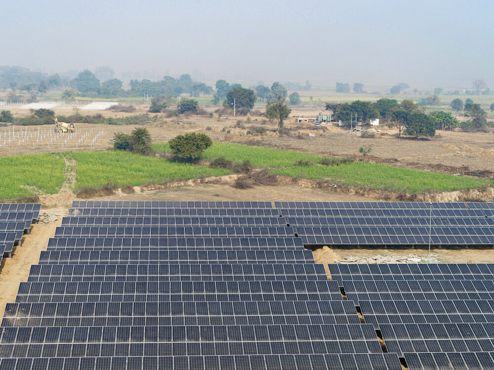
- Variable structural tilt
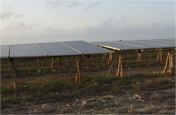
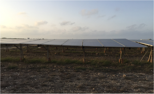
There is a site in Gujarat with evident intra- and inter-string variable structural tilt along with variable azimuth tilt, which caused shadow on another table adjacent to it. Variation in tilt was as high as 4° because of which the adjacent tables were receiving variable radiations differing by as high as 2%.
It was estimated that the non-optimally tilted table would cause an average reduction of 1% in the radiation annually. Also, the tables receiving less radiation would be generating 1% lesser power than the remaining tables.
Similarly, variation in azimuth angle was as high as 3° in some of the adjacent tables, which caused the radiation variation in the adjacent tables leading to mismatch loss.
This impact could be much higher if there is variation in both tilt and azimuth. Apart from the generation loss, this will also cause accelerated degradation due to mismatch and higher temperatures in affected tables.
- Unstable structures
The strength of the structure is tested when there is a high wind in the region. We have observed a high level of vibrations and noise around the tables at such times.
The reason might be loose braces and/or unstable structures. Another possibility could be inaccurate assumptions of a maximum wind speed or even ignorance of the fact that the region under consideration falls under the higher wind speed zones. These structures also had torsional stresses with changing azimuth angles.
- Season tilt specific issue
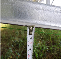
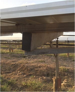
In seasonal tilt trackers, we have observed that the forward brace is quite weak sometimes. Even under just the dead weight of the PV panels, it forms a “bow” with a close to 9-12 mm deflection at the center.
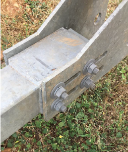
- Inappropriate tightening of clamps and nuts and bolts at cross bracing
This may not look like a big concern at the time of installation but if the clamps or nuts and bolts are not tightened properly, they can cause some serious damage to the structure.
This issue was noticed in one of the sites in Gujarat where clamps and nuts and bolts weren’t tightened properly at cross bracing.
As a result, braces started coming out and weakened the support of the tables. Clamps also got loosened and came out.
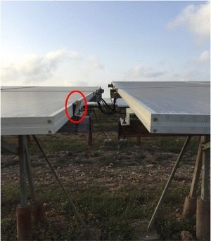
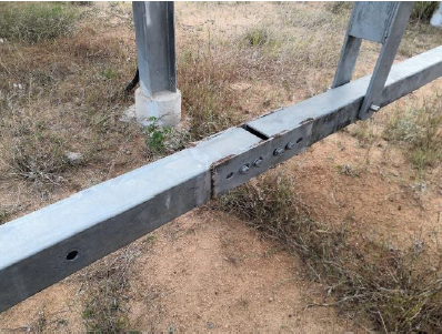
- Improper tightening of braces
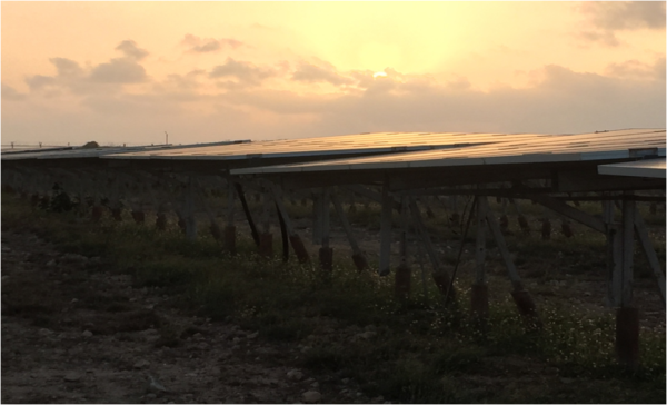
On the same site, another major fault was observed. Due to the improper tightening of braces, the whole table rotated on its axis and changed the tilt angle. As a result, there was high intra- and inter-row shading among adjacent tables, leading to power loss. Shadow existed on the modules for more than 3 hours on a summer day, which adversely affected the generation.
It was estimated that around 10% of the tables might be facing this issue, causing an estimated loss of about 1% in a year. This may also cause accelerated degradation in the shaded modules.
- Less ground clearance for the driveline
This issue was encountered at a plant with trackers. The driveline drives the rotation in the torque tubes for all the rows in one block or array. During the monsoon, flowing water and soil clog beneath the driveline.
When this happens, the tracker’s block movement is obstructed and might stop, which can be observed via the actuator’s electrical signature. The O&M team then has to immediately mobilize and take necessary action, such as closing the actuator, clearing the blockage and digging some more around it as future insurance.
To avoid this, permanent V-drain type structures can be created below all drivelines, lined with ‘rubble soling’ to maintain the shape.
Another difficulty observed because of this low driveline was that it connected to a low lying actuator which has risk of inundation of poorly draining soils like clays. V-drains were again suggested to handle this situation.
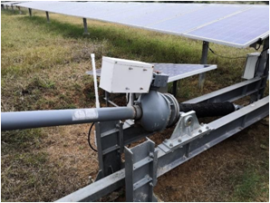
- Driveline slip due to slotted joints
In the same location, the driveline was connected directly to the torque struts of all the rows via a “true” pin, which allows relative rotation between the strut and the driveline. The driveline is supposed to act as a rigid member to rotate all the torque struts identically. Since a single driveline is not possible for the entire array, the driveline is broken into segments and connected.
Note that giving slots for this connection along the driveline is a major gamble. Slotted joints often slip and can result in improper operation of the whole tracker block. The motion of the driveline may not be translated correctly to the rotation of the subsequent torque struts. In this case, slotted bolts can be welded and a permanent connection created.
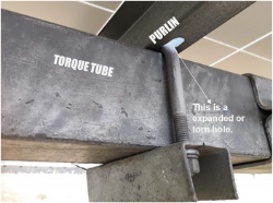
- Badly formulated Purlin to Torque Tube connection
Purlin should be rigidly connected to the torque tube such that the torque tube can achieve rigid rotation of the Purlins and eventually the panels.
The connection was found to be badly articulated and resulted in tearing and enlargement of the purlin hole, thus resulting in a “wobble” of the purlin on the tube. This could prove catastrophic for the tracker, for any appreciable wind speed above 60 mph as there will be galloping or flutter of the panels+purlins, similar to a flag on a post, thus causing irreparable damage to the PV module.
The issue can be resolved by fortifying the connection using plated or appropriate stiffening items.
- No scope of expansion to the modules
In a plant in Rajasthan the EPC did not provide scope for expansion to the modules. As a result, the frame of the modules started bulging because of excessive heat in the region. The moisture started penetrating within the modules and reduced insulation resistance, because of which there were repeated cases of tripping of the inverters.
The O&M team bypassed the ground fault detector/interrupter (GFDI) to prevent the tripping of inverters instead of solving the problem of insulation resistance and module expansion. By-passing GFDI further led to excessive potential induced degradation (PID) in the plant leading to power loss.
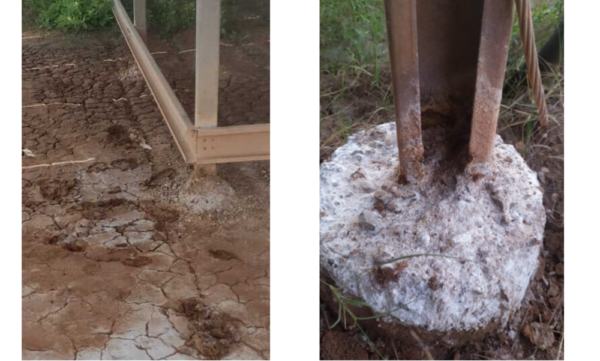
- Construction of a site on the basin of a salt lake
On another site in Rajasthan located on the basin of a salt lake, the structures had high levels of corrosion due to the highly corrosive nature of the soil and the hollow design of columns. Water collection inside the hollow columns further corroded the structure from inside.
This can be rectified by repainting the structures with epoxy zinc coating to slow down the corrosion. The use of water for module cleaning provided moisture that accelerated the rate of corrosion. In such a case the frequency of water-based cleaning can be reduced to once in a month.
Apart from this, structures can be cleaned using low-power air-blasts to remove salt and soil deposits. To overcome the problem of waterlogging, drain holes can be created at the bottom of the structure.
PV Diagnostics is a team of IIT Bombay graduates who are experts in diagnostics of solar power plants, quality control of modules for newly commissioned solar power plants and freshly procured modules. It provides end-to-end health check-up of solar power plants.
The views and opinions expressed in this article are the author’s own, and do not necessarily reflect those held by pv magazine.
This content is protected by copyright and may not be reused. If you want to cooperate with us and would like to reuse some of our content, please contact: editors@pv-magazine.com.


If the slotted angeal fiting was not proper the opportunity on soler peanal is perfect thean it shuead must proper fiting is there.
Apart from the technical issues you have mentioned, the Indian solar industry is hampered by the chronic structural issues like supply chain bottlenecks, weak domestic solar panel manufacturing industry and lack of skilled manpower.
Due to the improper tightening of braces, the whole table rotated on axis and changed the tilt angle.