From pv magazine, January edition.
Fun fact: Camels have blood vessels behind the brain that are connected to a network of fine ventricles in their nostrils, meaning blood can be cooled by around 4°C through respiratory evaporation, chilling the animal’s brain selectively in isolation from the rest of its body temperature. The mechanism allows camels to sustain extreme heat without breaking a sweat, thus retaining their internal water reserves. Also, a camel can close its nostrils to keep out fine dust blowing through a desert. Millennia of evolution have delivered a biological solution power electronics suppliers increasingly require as distributed MENA solar markets emerge.
The insulated-gate bipolar transistor (IGBT), an inverter’s ‘heart’, produces considerable amounts of heat while switching. At the same time, IGBTs, printed circuit boards and other electrical equipment start operating at lower efficiencies when they reach a certain temperature. An increase of just 1-2°C above the maximum operating temperature – usually 90-110°C – can cause equipment lifetime to halve.
To avoid this, inverters lower their power output through derating. This, however, has significant effects on a plant’s levelized cost of electricity (LCOE). The more efficient an inverter’s cooling mechanism, the later derating occurs. A quick look at inverter datasheets shows that most inverters can maintain operations at a maximum ambient temperature of around 60°C, but start derating at slightly above 40°C. Not all suppliers provide data on different outputs under different ambient temperature scenarios, but those which do, admit power losses of between 5% and 10% at an ambient temperature of 50-55°C, compared to 30°C.
Also, different models from the same supplier can have severe differences in derating behavior – with some severely derating at 35°C – suggesting different heat management solutions were deployed. Of course, inverters don’t need to sustain ambient temperatures of more than 45°C if they are being deployed in many parts of Europe or North America. It is clear, however, EPCs are well advised to bear the issue in mind when planning in India and the Middle East.
Beat the heat
Most high-power string inverters utilize forced air cooling, employing fans mounted on a heat sink. Speaking to pv magazine, Andreas Schlumberger of TÜV Rheinland said passive cooling systems for inverters above 10 kVA are rare. Higher powered string inverters dissipate heat through pipes and convection zones to a larger heat sink on the outside of the inverter, where no fan is mounted. Huawei, for example, supplies inverters with this type of cooling.
Manufacturers such as Fronius or SMA rely on forced air cooling. This means heat is dissipated through pipes to a smaller heat sink onto which a fan is mounted. The use of a fan increases cooling power, which makes for a system of choice for most manufacturers of high-power string inverters.
SMA’s Andreas Tügel, technical product manager for the inverter product group, said he believes passive cooling does not provide the necessary flexibility to react to changing irradiation levels caused by passing cloud cover. “It is absolutely crucial to implement an actively controlled cooling system – like speed controlled fans – which can adapt the cooling grade based on the currently available share of PV power,” he said. For him, passive systems are not reliable enough to sustain changing heat patterns for more than 25 years. Fronius holds a similar position and points to passive cooling being prone to hotspots, which strain internal components.
On the other hand, Huawei says it places heat generating components and heat sensitive parts in different compartments within inverters while utilizing various thermal insulation strategies. This way, the build-up of hotspots in sensitive areas can be avoided. Huawei says the benefit is better dust protection because there are no air inlets. It is important to note, however, that also with forced-air-cooled string inverters, the inside of the inverter is seldom exposed to dusty external air.
Different methods
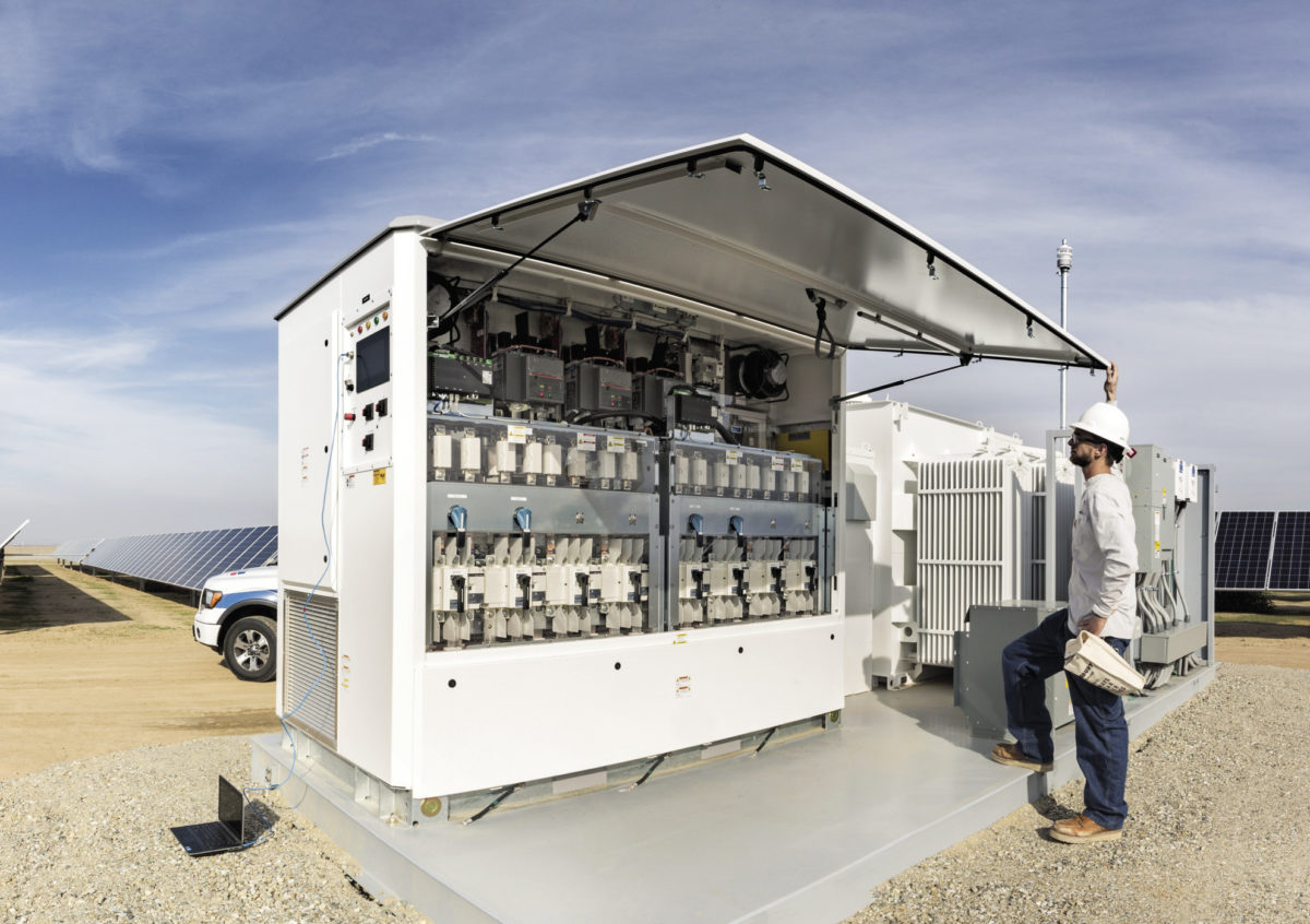
Cooling methods for central inverters also differ between manufacturers. Siemens, for example, uses a combination of air-to-air heat exchangers and a liquid-to-air heat exchanger. Dorko Eliaszewskyj, technology director for utility-scale PV at Siemens AG, said the liquid – a mixture of water and glycol – is actively pumped past the power stacks, which generate the most heat. The air-to-air heat exchanger cools the remaining areas inside the cabinet.
Through this process, outside air never really gets into contact with the interior air. Instead, a heat exchanging technology analogous to that used in the auto and air conditioning industries is deployed. Because the cooling systems are not purpose-built for the central inverters they are cost competitive, with thousands of hours of validation across different applications. By contrast, SMA uses an architecture which doesn’t use liquid cooling for the power stacks. Instead, a powerful heat exchanger sucks in air two meters above ground to cool the circulating air on the inside of the inverter.
The company has deployed its systems in extreme conditions in Jordan, the Australian outback and the deserts of Mauritania, and holds that its central inverters are designed for operations above 50°C. Such temperatures are surpassed rarely in any region.
Dust – only an O&M challenge
Inverters, it appears then, are as sealed as a camel’s nostrils. The interior hermetically sealed. If fans are used to cool inverters, they are mounted onto a heat sink that dissipates heat from the interior to an outside cooling element. All inverters are marked with an IP number, usually between 65 and 67. The first number shows sealing level to dust and the second to water. Thereby, IP 67 is “dust tight” and protected against water jets and waves. The inside of the inverter may be a high-power string inverter or a central inverter that never actually comes into contact with the air outside. Whatever heat dissipation system is deployed, it is a closed system working with heat sinks and heat pipes. Dust, then, only becomes an O&M challenge, insofar as dust must be removed from the outside of heat sinks or fans.
To demonstrate the effectiveness of sealing, most prominent manufacturers boast that their products have been tested under unnaturally extreme dust conditions, with particles considerably smaller than naturally occurring dust. As a result, the likelihood of an inverter being damaged through dust ingress is reasonably limited. However, O&M can account for a considerable part of a PV project’s LCOE. Manufacturers claim their systems are maintenance free, with some claiming competitors’ systems incur hefty O&M bills. TÜV Rheinland’s Schlumberger believes, in principle, no system is maintenance free, but he also does not report any striking failures.
Liquid-cooled systems, unless they work with high pressure, are usually low maintenance. However, if a problem arises it is likely to be more complicated to fix, not to mention the environmental issues that could arise if coolant leaks into the soil or atmosphere. If the central inverter is containerized and located in a small building, and uses a gas-based coolant, O&M staff could also be required to enter the compartment with gas mask equipment to avoid the health impacts of fumes inside.
Though containerized solutions may be impractical in hot climates, shading the inverter is presented as a rather simple and effective solution. Both TÜV’s Schlumberger and some of the manufacturers advocate shading.
Next steps in inverter evolution
Siemens’ Eliaszewskyj sees that with the evolution of inverter topologies and materials, significant progress is being made in reducing inverter operational temperature. The switch from two to three-level architecture allowed for more efficient and higher frequency switching without using higher voltage and higher heat IGBTs. In so doing, both power density and efficiency can be increased.
A few years ago, few inverters with efficiencies in excess of 98% were supplied. In this vein, Eliaszewskyj said that for a 5 MW inverter, the losses, for example, have the same impact on power output as driving a 2 kW heater fan.
Eliaszewskyj believes it is likely the use of silicon carbide MOSFETs in inverters will become far more commonplace. These transistors allow for a faster and more efficient switching process that generates far less heat. He added, MOSFETs are also less sensitive to heat and can maintain switching properties through a wider temperature range.
Looking further ahead still, gallium nitride-based semiconductors demonstrate better performance under high heat, which could be of great use. Schlumberger, of TÜV Rheinland, believes this could be an area in which activity could pick up within supplier ranks.
Eliaszewskyj adds, however, that while less heat will be produced through higher efficiencies, manufacturers are likely to offset the effect by increasing the power density of future inverters, to increase competitiveness. Hence, efficient cooling will continue to be a requirement irrespective of efficiency gains. What is likely, is that manufacturers will have to strike a delicate balance between cooling methods, materials used, derating and power density. Getting that balance right, particularly as it pertains to component and project economics, will be no easy task.
SMA’s Tügel, for example, says that while it would be technically possible to design an inverter to start derating at higher heat, the production gains on a few occasions per year would be offset by the additional CAPEX of the inverter.
It took the camel thousands of years to adapt to the climate of the deserts. Power electronics have only had a few years. While great developments have been achieved already, the present shortcomings can easily be mitigated.
Aside from avoiding placing the inverter in the direct sun, project developers are well advised to study the temperature data of their proposed plant location. The data should be matched with the manufacturer’s derating curves, to identify the average losses throughout the year
This content is protected by copyright and may not be reused. If you want to cooperate with us and would like to reuse some of our content, please contact: editors@pv-magazine.com.


By submitting this form you agree to pv magazine using your data for the purposes of publishing your comment.
Your personal data will only be disclosed or otherwise transmitted to third parties for the purposes of spam filtering or if this is necessary for technical maintenance of the website. Any other transfer to third parties will not take place unless this is justified on the basis of applicable data protection regulations or if pv magazine is legally obliged to do so.
You may revoke this consent at any time with effect for the future, in which case your personal data will be deleted immediately. Otherwise, your data will be deleted if pv magazine has processed your request or the purpose of data storage is fulfilled.
Further information on data privacy can be found in our Data Protection Policy.