
Harnessing the power of the sun, PV systems are transforming the way we generate electricity. However, while the sun’s energy is abundant, harnessing it effectively in all conditions remains a challenge. One of the significant hurdles that PV systems face is the issue of partial shading.
Max Performance Under Partial Shading
PV generators mounted on rooftops often encounter varying degrees of shade. The complexity of this challenge lies not in the presence of shade itself, but in understanding how to navigate it. Surprisingly, the solution isn’t necessarily about introducing more sophisticated power electronics to the system. In fact, for most rooftop systems, this isn’t the path to peak performance (see Fig. 1). The effectiveness of power electronics hinges on various factors, such as the degree of shading, the number of PV modules in a single string, and the overall size of the installation.
As owners and PV planners seek answers to this intricate problem, they can find insights from conference presentations and the upcoming technical report from IEA-PVPS Task 13, available on the IEA-PVPS website. These resources shed light on a topic that has puzzled experts for decades.
These three wiring variants are common in solar power roofs today, although the use of MLPE components, like DC/DC optimizer has increased in the last decade.
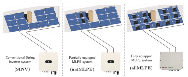
Fig. 1: Cyril Allenspach / ZHAW Master Thesis 2023, Switzerland
The Evolution of PV Technology
Over half a century ago, the introduction of bypass diodes in PV modules was a game-changer. These diodes acted as conduits to redirect current flow in cases of partial shading with remarkable efficiency.
Yet, the journey of PV technology has been marked by constant evolution. New DC/DC converters have taken the reins, offering the potential to operate each PV module at higher voltage values with lower module currents. This innovation outshines the simple serial connection of all modules to power the conventional string DC/AC inverter.
However, it’s essential to note that this isn’t a one-size-fits-all solution. The situation where DC/DC optimizers shine is relatively rare, typically occurring when a single solar cell in the module is shaded by no more than 40%, and three bypass diodes are used. While the theoretical potential for energy gain with DC/DC optimizers is promising, it must contend with real-world losses, which typically account for about 2% of the annual yield, significantly higher than traditional PV module serial connectors.
Understanding Data Sheet Values
In the current market, customers are presented with offers for DC/DC optimizer PV systems for their single-family homes. These offers often flaunt impressive data sheet efficiency values, with claims of 99.5% efficiency and average efficiency values of 90%. Based on these figures, local PV experts may recommend these systems as the most efficient choice. However, there’s a nuance in these numbers that often escapes casual observation.
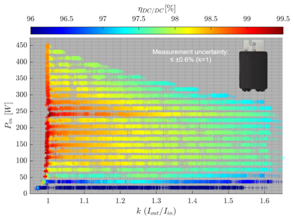
Today’s datasheet values are a rare sighting and are typically found in cases where the optimizer operates in a specific mode known as k = 1. This mode is where the optimizer functions as an ohmic resistance rather than a DC/DC voltage converter. This specific mode, depicted on the left side of Figure 2, represents a unique scenario that doesn’t reflect the daily reality of most PV systems. Nevertheless, over 100 million of these optimizers have been installed worldwide, predominantly on small-scale rooftops.
However, there’s a catch in interpreting these impressive efficiency values. In the past, DC/DC manufacturers often advertised double-digit percentage yields, which, unfortunately, customers sometimes misinterpreted as the system’s annual yield rather than performance in specific shading moments. This discrepancy underscores the importance of not merely relying on impressive figures but diving deeper into the practical implications of these systems.
Challenges in PV Planning
One of the challenges in the world of PV planning is the reliance on typical commercial PV planning tools that tend to overestimate the capabilities of DC/DC components. These tools often rely on the above data sheet values as an average for all optimizers within the system. However, they may not adequately consider the complex shading situations of each cell in the module, the role of all bypass diodes, or the orientation of the module on the roof.
These tools used by PV planners typically estimate the average module power output relative to the percentage of the shaded module area. While this provides a basic overview, it doesn’t account for the intricacies of partial shading scenarios. The result is often an inaccurate reflection of real-world performance.
Popular Findings
The complexity of addressing partial shading has led to in-depth research and findings that offer valuable insights. The Zurich University of Applied Sciences (ZHAW; German: Zürcher Hochschule für Angewandte Wissenschaften) annual simulation results, based on shading analyses of each individual solar cell, paint a clear picture. These models are built on the losses of commercial DC/DC optimizers measured indoors at relevant operating points. The losses observed are approximately 2% lower than the manufacturers’ data sheet information, a significant variance that has been documented in various conferences, papers, and magazines.
The outcomes under different shading conditions are enlightening and offer practical guidance:
- Light Shading Conditions:
In scenarios with little to no shading or light shading conditions, such as a single chimney casting a slight shadow, the conventional string inverter typically performs equally as well or even more efficiently. This is achieved through the serial connection of standard PV modules equipped with three bypass diodes using SINV.
- Medium Shading Conditions (Fig. 3):
When light shading intensifies slightly, as with the presence of another small exhaust pipe next to a chimney or a dormer shading the PV modules, local optimizers used occasionally (e.g., 1-4) can deliver optimal yield. These independent optimizers outperform systems that incorporate losses from optimizers that either don’t supply power to shaded modules or do so only sporadically. The advantages extend to shading-tolerant modules equipped with more than three bypass diodes, making them the preferable choice when a group of PV modules faces shading.
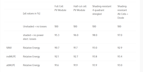
Fig. 3 Annual performance of several power electronic systems (see Fig. 1) and PV module types for shading of the PV roof generator, between category light to medium shading, by a chimney using commercial DC/DC optimizer
(See F. Baumgartner, C. Allenspach, EUPVSEC 2023, Lisbon and C. Allenspach, F. Baumgartner et. al. Sol. RRL 2022, 2200596)
- Heavy Shading Conditions:
In instances of substantial shading, such as a dormer casting shadows on some modules and additional shading from neighboring buildings, installing an optimizer behind each module can substantially increase the annual yield. This approach is particularly beneficial when compared to unshaded conditions, where the annual yield may decrease by up to 10% or more.
- Shading on Small Strings on the Roof:
The market currently lacks highly efficient low DC voltage string inverters that can utilize approximately four to ten PV modules in a single string. However, this gap is addressed by DC/DC optimizers that can accommodate various module orientations within small strings. Additionally, the introduction of new half-cell butterfly PV modules, with all half cells connected in series at higher PV module voltages, offers a promising solution.
In summary, shading-tolerant modules can potentially yield up to a 2% increase in annual yield combined with the use of SINV, while the use of Module Level Power Electronics (MLPE) optimizers results in a more modest 1% increase without shading-tolerant modules. However, it’s important to note that the absence of a PV module situated behind a chimney leads to the Single Inverter (SINV) either being more efficient or equally efficient, as detailed in the EUPVSEC 2023 paper (see Fig. 3).
Optimizing PV Plant Design
The design of an optimum PV plant hinges on the selection of one of the three PV power electronic systems. Whether to opt for standard PV modules or shading-tolerant PV modules is a decision with long-term implications. In the years to come, a wider range of the latest PV module products, along with new low-voltage PV inverters and multiple Maximum Power Point Tracking (MPPT) inputs, will become available. These developments aim to facilitate the creation of long-term, robust systems that are both efficient and environmentally friendly.
Cost Considerations and Future Insights
PV inverters typically require replacement once during the 25 years of PV plant operation. However, the scenario becomes more complex when it comes to DC/DC optimizers. Operating at significantly higher temperatures on the roof, these electronics may face more frequent replacement needs. In Switzerland, a country with a robust market for single-family houses, it’s common to budget for replacement costs ranging from about 1000 to 3000 Swiss Francs. These costs often include fall protection measures, further underlining the financial aspect of optimizing PV systems.
The Need for Informed Decision-Making
In a fair market, end customers must gain a clear understanding of the various options available for their PV rooftop system. Choices range from string inverters and independent optimizers to all optimizers and the use of individual shading-tolerant modules. It’s not just about assessing potential electrical performance gains; it’s also crucial to consider the associated risks of possible replacement costs. With these factors in mind, customers can make informed decisions that align with their long-term goals and budgetary constraints.
Collaborative Efforts for Improved PV Planning
The exchange of factual information among different stakeholders in the PV industry is a catalyst for progress. The development of improved commercial PV planning tools and an enhanced experience for PV system planners are the results of this collaboration. IEA PVPS Task 13 is at the forefront of these efforts, with plans to publish a final report in 2024. This report will include recommendations from international experts, coordinated by ZHAW, aiming to guide the industry toward more effective and efficient PV system planning. The report will be available at Reliability and Performance of Photovoltaic Systems – IEA-PVPS
Author: Franz Baumgartner, ZHAW Zurich University of Applied Sciences, Switzerland
This article is part of a monthly column by the IEA PVPS programme.It was contributed by IEA PVPS Task 13.
The views and opinions expressed in this article are the author’s own, and do not necessarily reflect those held by pv magazine.
This content is protected by copyright and may not be reused. If you want to cooperate with us and would like to reuse some of our content, please contact: editors@pv-magazine.com.


By submitting this form you agree to pv magazine using your data for the purposes of publishing your comment.
Your personal data will only be disclosed or otherwise transmitted to third parties for the purposes of spam filtering or if this is necessary for technical maintenance of the website. Any other transfer to third parties will not take place unless this is justified on the basis of applicable data protection regulations or if pv magazine is legally obliged to do so.
You may revoke this consent at any time with effect for the future, in which case your personal data will be deleted immediately. Otherwise, your data will be deleted if pv magazine has processed your request or the purpose of data storage is fulfilled.
Further information on data privacy can be found in our Data Protection Policy.