From pv magazine 06/2022

In September 2021, Longi, JA Solar and Jinko formed an alliance to standardize the use of M10 wafers. To turn this wafer format into the new go-to standard requires more module makers to join the alliance. Have you seen interest from other manufacturers to join up?
Together, Longi, JA Solar and Jinko sell more than half of modules using M10 wafers globally. When Longi, JA Solar and Jinko standardized M10 module dimensions in September 2021, it gained great attention from partners throughout supply chain and was very well received by the whole industry, both upstream BOM materials suppliers and downstream BOS [balance of system] partners. It has been established as an industry standard, as other M10 module suppliers are quickly following the trend and adopting the standard into their module design.
What are the advantages for the industry to have such an alliance?
With the standardization of M10 module dimensions, many related BOM materials, such as the glass, frame, and EVA, will all have unified dimensions, which helps to streamline manufacturing processes and save on cost. M10 module dimension standardization also makes it easier for downstream BOS partners to maintain racking compatibility, and to minimize design changes with different module dimensions. It is a cost saver for both upstream and downstream partners, as well as end customers.
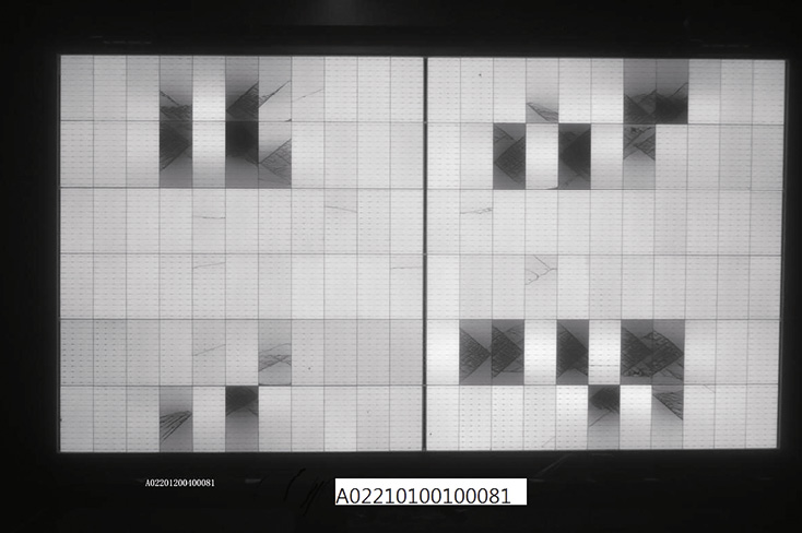
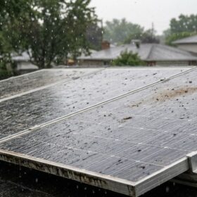
All modules, irrespective of wafer size, must pass several stress tests. In your findings you note, however, that modules that measure 1.3 meters on the short edge instead of 1.13 meters, bend the front glass 40% more under the same mechanical loading. What does this mean to the longevity of the cells, and why hasn’t this shown in the IEC test protocols?
It is well understood that the IEC certification test standard is not sufficient to ensure module lifetime of 25 to 30 years under different environmental conditions. As PV projects are built to generate electricity consistently for 25 to 30 years, and extreme weather conditions become more and more common, PV system design, including modules, needs to demonstrate sufficient margins to survive extreme weather.
As the center of the module is only supported by glass, we have found during mechanical loading tests that 1.3m wide modules (210-66 cell) deformation is 40% to 60% higher than 1.13 meter modules (182-72 cell). As a result, lots more microcracks formed on 1.30 meter-wide modules than 1.13 meter modules, and power loss is significantly higher. It is a reliability risk.
How much does the 40% increase in bending increase the risk of cell cracking?
In the 5400Pa SML+1000Pa DML+TC50 sequence test, it is found that the power loss due to microcracks with a 1.3 meter module is 6.65%, which is higher than IEC standard, at 5%, while the power loss with 1.13 meter module is 2.90%.
Given the bending and pressure risks you have set out, what prevents module makers from using glass-glass modules with thicker, more rigid front-glass to ensure the stability of bigger wafer modules?
To reduce deformation under load, thicker glass can be used to minimize reliability risks with oversized modules – using 66 210 mm cells. However, the weight of a 210-66 cell module already approaches 40 kg with dual 2mm glass. Thicker glass will increase it further and make it harder for installation handling. Thicker glass will also increase module cost as well.
With the introduction of the new wafer sizes, the long edge of modules has grown from 1.7 to 2.4 meters, depending on the manufacturer and module-type. Why is a longer long edge apparently less critical? And is there an optimal length for the long edge?
It is not that a long edge is less critical, but a long edge is less sensitive to the increase in length, as its strength can be improved with improved frame design. It becomes more and more difficult though, as module length increases from 1.7 meters to 2.4 meters. Consequently, longer modules result in larger sail width for trackers, which requires more steel for torque tube and piles, and a higher cost. As module width increases, the strength of a long edge frame has less and less influence on the center of a module, as its strength is governed by glass.
Together with TÜV Nord, Longi tested the working temperature of modules using M10 and M12 wafers. The M10 wafers appeared to provide a higher energy yield per watt. Can you explain why?
The test results initially are from a JA and TÜV Nord pilot project at Yinchuan, China. Longi has also conducted pilot research in Xi’an and Taizhou, with recently obtained data confirming that M10 modules tend to outperform ultra-large current modules, made with 210 mm wafers, in terms of energy yield performance, the higher the irradiance, the higher the energy yield.
The energy yield performance difference for small and large current modules is mainly attributed by the irradiance and working temperature factors. Fraunhofer CSP and ISC both verified this theory in the research of full-cell and half-cut cell module comparison studies. The same theory is also applicable for explaining the energy yield difference between 182 and 210 modules, which indicated that lower working temperatures make 182 module perform better under high irradiance conditions.
What steps can project developers and investors take to lower their risk?
It is clear modules made with M10, or 182 mm, wafers demonstrate better reliability performance with wider supply base. We have exhausted benefits of large format modules with M10-72 cell design. Future advancements on technological innovations will focus on cell and module efficiency improvement instead of making larger modules. Future modules with advanced technology will be based on the M10-72 cell format standardized dimension.
This content is protected by copyright and may not be reused. If you want to cooperate with us and would like to reuse some of our content, please contact: editors@pv-magazine.com.


By submitting this form you agree to pv magazine using your data for the purposes of publishing your comment.
Your personal data will only be disclosed or otherwise transmitted to third parties for the purposes of spam filtering or if this is necessary for technical maintenance of the website. Any other transfer to third parties will not take place unless this is justified on the basis of applicable data protection regulations or if pv magazine is legally obliged to do so.
You may revoke this consent at any time with effect for the future, in which case your personal data will be deleted immediately. Otherwise, your data will be deleted if pv magazine has processed your request or the purpose of data storage is fulfilled.
Further information on data privacy can be found in our Data Protection Policy.